JudoMapper: Tool Logic and Architectural Choices
1. Purpose and Scope
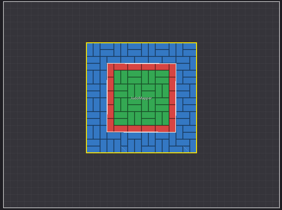
JudoMapper is a desktop planning tool for arranging judo contest areas inside a sports hall. It lets a user add and position areas, configure their dimensions, inspect spacing and overlap warnings, choose a tatami-laying pattern, and estimate the required tatami materials.
The application is built in C++17. SDL3 creates the window, handles platform events, and provides the rendering backend. Dear ImGui supplies the immediate-mode user interface. The project is split into a small set of headers and source files so that the domain model, layout calculations, user interface, and drawing code can be understood separately.
This document describes the current implementation and the reasons for its main architectural choices. It is not a claim that every concern is fully isolated: some canvas interaction logic still lives alongside canvas rendering.
2. The Main Concepts
2.1 A contest area (Field)
A tatami::Field represents one square judo area. Its main properties
are:
id: a stable identifier used to select, find, duplicate, or remove the area.name: the label drawn on the plan and shown in the interface.x,y: the area's top-left position in the hall's coordinate system.contest: the size of the contest square, in metres.danger: the width of the danger-zone border.safety: the width of the safety border around the contest area.
The full footprint is calculated as contest + 2 * safety. The danger
zone is contained within the contest square; the safety zone surrounds
it. Field::zoneAt() classifies a cell as outside the field, safety,
danger, or contest.
Positions and dimensions are represented as integer metres. This keeps the planning model grid-based and makes keyboard movement and tile placement predictable.
2.2 Zones and priority
tatami::Zone defines four ordered values: None, Safety, Danger,
and Contest. The ordering is intentional: when two fields cover the
same cell, the layout builder keeps the zone with the higher value. This
means contest cells take precedence over danger cells, which take
precedence over safety cells.
The priority rule makes overlaps deterministic. It does not make an overlap valid: overlap checks separately flag intersecting contest areas.
2.3 Tatami and material statistics
A tatami::Mat records a tile's position, width, height, and zone. A
full mat occupies a 1 × 2 metre rectangle; a half-mat occupies a 1 × 1
metre cell. tatami::Stats counts full and half mats, and
tatami::Layout groups the generated mats with per-zone statistics.
These are plain data structures. They describe results rather than
owning application behaviour, so struct is appropriate: the data is
intended to be straightforward to inspect and pass between functions.
2.4 Patterns
The tatami::Pattern enumeration defines four placement strategies:
- Aligned --- tries a horizontal tile first, then a vertical tile.
- Vertical --- tries a vertical tile first, then a horizontal tile.
- Brick --- tries horizontal placement only on alternating cells, producing a staggered layout; cells that cannot be paired become half-mats.
- Basket weave --- alternates horizontal and vertical preference in 2 × 2 blocks.
A tile is never allowed to span cells belonging to different zones. Any non-empty cell that cannot be paired under the selected pattern becomes a 1 × 1 half-mat.
3. How the Layout Is Calculated
The core algorithm is implemented in LayoutBuilder.cpp, independently
of SDL and ImGui.
Step 1: Find the occupied bounds
The builder calculates the smallest rectangle that contains all fields. It uses these bounds to create a temporary grid. The grid is based on the fields' world coordinates, so fields do not need to start at the origin.
If there are no fields, the builder returns an empty layout.
Step 2: Rasterize fields into zone cells
Every cell covered by a field is assigned a zone using
Field::zoneAt(). If multiple fields cover the same cell, the
zone-priority rule keeps the highest-priority zone.
Rasterization turns the geometric problem into a discrete grid problem. That makes tile pairing, statistics, and zone boundaries easier to handle consistently.
Step 3: Tile each zone
The builder scans the grid and tracks which cells have already been used. At each unused, non-empty cell, it tries to place a 1 × 2 tile according to the chosen pattern. Both cells must be free and belong to the same zone.
If no legal pair can be placed, the builder places a 1 × 1 half-mat. Each placement updates the tile list and the full/half counters for that zone.
The pattern's preference is based on global coordinates, not just the temporary grid's local origin. This is important for patterns such as Brick and Basket Weave: adding or moving another field should not unnecessarily shift the pattern everywhere else because the grid's bounding box changed.
Step 4: Validate the field arrangement
checkFields() returns a set of issue flags for each field:
- Overlap --- the contest areas intersect.
- Shared gap too small --- the distance between contest areas is below the configured minimum.
- Outside hall --- the full field footprint extends beyond the configured hall dimensions.
The overlap and minimum-gap calculations compare contest-area rectangles. The hall-boundary check uses the full footprint, including the safety area. The results are stored per field so the interface can display warnings and the renderer can highlight affected areas.
The layout builder and validator are ordinary C++ functions. They can be tested without opening a window or starting the UI framework.
4. User Interaction and Drawing
Adding and editing areas
The palette in the side panel lets users create a new field by clicking
a size or dragging it onto the plan. New fields receive a unique ID and
a name based on the current language (Area N or Terrain N). The
selected field can then be edited, duplicated, or deleted.
The App structure stores the current session state, including:
- the list of fields and the next ID to assign;
- the selected field and the active tatami pattern;
- hall dimensions and the minimum shared-gap setting;
- the selected language;
- canvas pan, zoom, and dragging state;
- the most recently generated layout and validation issues.
The state is kept in one place and passed to the UI and renderer. This is a pragmatic fit for a small single-window application: it makes the flow of data explicit without introducing a more complex state-management framework.
Canvas coordinate handling
The renderer maps between world coordinates (metres) and screen coordinates (pixels). Pan and zoom control this mapping. The user can zoom with the mouse wheel, pan with the middle mouse button, and move the selected field with the arrow keys. The canvas also draws the hall, tile rectangles, zone colours, field outlines, field names, selection highlights, and issue indicators.
The current drawCanvas() implementation combines drawing with some
input handling and state updates. Keeping these together is simple while
the canvas behaviour is small, but it does mean rendering is not a
purely visual operation. If interaction grows, input processing could be
extracted into a separate canvas-controller module.
5. Architecture and File Responsibilities
The project uses a simple include/ and src/ layout. The goal is to
separate code by responsibility without creating many tiny directories
or introducing unnecessary abstraction.
File or group Responsibility
Field.hpp, Mat.hpp, Domain data structures for fields,
Stats.hpp, Layout.hpp tiles, statistics, and generated
layouts
Zone.hpp, Pattern.hpp Enumerations describing zone types
and tile patterns
LayoutBuilder.hpp/.cpp Pure layout generation and field
validation logic
App.hpp/.cpp Application state and basic field
operations such as finding, adding,
and removing fields
UI.hpp/.cpp Dear ImGui panels, controls,
palette, and editing interface
Renderer.hpp/.cpp Canvas drawing and closely related
canvas interactions
Language.hpp, Language selection and translation
Translations.hpp/.cpp lookup
main.cpp SDL3 setup, ImGui initialization,
event loop, frame lifecycle, and
shutdown
CMakeLists.txt C++ build configuration and
SDL3/ImGui dependencies
Why the layout algorithm is separate
The most important separation is between domain calculations and the
graphical interface. LayoutBuilder.cpp works with fields, patterns,
zones, and grids; it does not need SDL or ImGui. This keeps the
algorithm easier to reason about and makes it possible to add tests for
layout generation and validation without running the desktop
application.
Why App is a state container
App groups the mutable state that needs to be shared by the UI and
canvas. It is currently a struct because its members are accessed
directly by those modules. That choice favours simplicity over strict
encapsulation. If the project later needs stronger invariants,
undo/redo, persistence, or more complex workflows, selected operations
could be moved behind methods or a dedicated controller.
Why the UI and renderer are separate
UI.cpp describes the side-panel controls and editing widgets.
Renderer.cpp is responsible for the spatial canvas and its visual
feedback. They share the same App state, which avoids duplicating the
model. The boundary is not absolute because canvas drawing currently
also handles some mouse and keyboard interaction.
Why use plain structures and enums
The domain model is mostly data: fields, tiles, statistics, and layouts.
Plain structs and enums make these concepts visible and inexpensive to
pass around. The code uses functions for operations such as
buildLayout() and checkFields() rather than giving every data
structure a class hierarchy. This avoids adding object-oriented
machinery where it would not currently provide a clear benefit.
6. Technology Choices
C++17
C++17 provides the language features used by the application while remaining broadly supported by modern compilers. The code uses standard-library containers and algorithms for field lists, grids, and validation.
SDL3
SDL3 creates the resizable application window, supplies events, and provides the renderer used by the ImGui backend. The main loop processes events, starts a new ImGui frame, draws the UI, renders the resulting draw data, and presents the frame.
Dear ImGui
Dear ImGui is an immediate-mode GUI library. The interface is described each frame from the current application state. This suits a compact tool with controls, editable values, tables, and a custom drawing canvas. It also avoids maintaining a separate retained widget tree.
CMake and FetchContent
CMake defines the executable, compiler settings, include directories, and linked libraries. The configuration first looks for an installed SDL3 package and can fetch SDL3 if one is not found. Dear ImGui is fetched and its core and SDL3 backend source files are compiled into a static library for this application.
This makes the dependency setup reproducible, although the first configure/build may need network access when dependencies are not already available.
7. Internationalization
The language is represented by the Language enum, with English as the
default and French as the alternative. UI labels are represented by
TextKey values and resolved through tr(language, key). Pattern names
use patternName().
Centralizing strings avoids scattering language checks throughout every UI widget. The selected language changes the displayed labels immediately. In the current implementation, the language is session state only and is not saved between launches. Area names are generated using the language active when each area is created; changing the language later does not automatically rename existing areas.
8. Current Trade-offs and Possible Next Steps
The current architecture is intentionally small. It separates the most algorithmically important logic but does not try to anticipate every future feature.
Potential next steps, if the application grows, include:
- Automated tests for
LayoutBuilder--- cover empty layouts, zone boundaries, each pattern, half-mat counts, overlaps, minimum gaps, and hall boundaries. - Separate canvas input from drawing --- keep rendering focused on visuals and move mouse/keyboard state transitions into a controller.
- Save and load plans --- serialize field dimensions, positions, names, hall settings, pattern, and language preferences.
- Undo and redo --- centralize edits as commands or snapshots rather than changing fields directly from multiple UI callbacks.
- Stronger state encapsulation --- replace direct public access to
Appmembers with methods if maintaining invariants becomes important. - Persist user preferences --- save language and other preferences if desired.
These are opportunities rather than requirements for the current tool. The existing structure is designed to be understandable first, while leaving the main calculation logic isolated enough to test and extend.
9. Summary
JudoMapper converts a set of square contest areas into a grid of zones, then tiles those zones with full and half tatami according to a selected pattern. It separately checks the field arrangement for overlaps, insufficient gaps, and hall-boundary violations.
The architecture follows the same flow: domain data is represented by
simple structs and enums; LayoutBuilder performs layout and validation
calculations; App holds the current session state; the UI edits that
state; the renderer visualizes it; and main.cpp manages SDL3 and Dear
ImGui. This is a deliberately straightforward architecture for a focused
desktop planning tool, with clear places to add tests and extract
responsibilities as the application evolves.