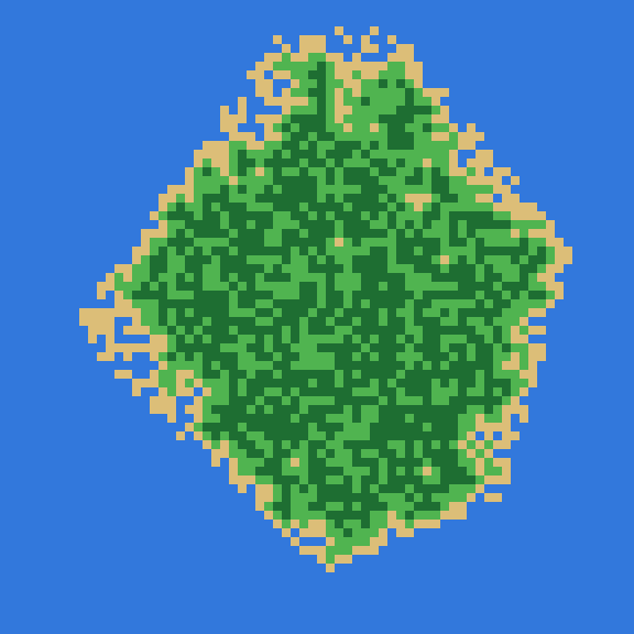
WFC Island — Project History
1. The Beginning — The Idea
WFC Island started as a personal experiment around procedural generation and Wave Function Collapse (WFC).
The initial goal was straightforward:
Generate an island procedurally using Wave Function Collapse.
The project was developed in C++20, with SDL3 used for rendering and Dear ImGui for the user interface.
At the beginning, the main question was not how to build a complete application, but rather:
How can WFC be used to generate a believable island?
This quickly revealed that there were actually two different problems to solve.
First, the program needed to create the shape of the island.
Second, it needed to decide which terrain tiles should fill that shape.
This distinction became one of the first major architectural decisions of the project.
2. First Step — Understanding Wave Function Collapse
Before building the complete generator, the core idea behind WFC had to be understood.
Wave Function Collapse is a constraint-based procedural generation algorithm.
Instead of immediately assigning one tile to every cell, each cell starts with a set of possible tiles.
For example:
Cell:
{Water, Sand, Grass, Forest, Rock}
The cell therefore has several possible states.
The number of remaining possibilities can be called its entropy.
5 possibilities → entropy 5
3 possibilities → entropy 3
1 possibility  → entropy 1
0 possibilities → contradiction
The basic WFC loop is:
Find the cell with the lowest entropy
              ↓
          Collapse it
              ↓
      Propagate constraints
              ↓
        Repeat the process
The important discovery was that WFC does not randomly choose every tile independently.
Instead, every decision affects neighboring cells.
3. Building the Grid
The next step was creating the grid on which WFC would operate.
The project eventually settled on a:
72 × 72
grid.
Each cell stores:
- Its current tile
- Its remaining possibilities
- Its entropy
The project introduced several tile/state types:
Unknown
Boundary
Water
Sand
Grass
Forest
Rock
Snow
Lava
Contradiction
An important distinction appeared here.
Unknown is not a WFC tile.
It represents a cell that has not yet been resolved.
Similarly, Boundary is a geometric state rather than a terrain tile.
Contradiction is a special state used when WFC has no valid solution for a cell.
This separation became increasingly important later.
4. Implementing the First WFC Operations
Once the grid existed, the core WFC operations were implemented.
The first important operation was resetting the possibilities of unresolved cells.
Conceptually:
Unknown cell
      ↓
All valid terrain tiles
      ↓
{Water, Sand, Grass, Forest, Rock, ...}
Then came the collapse operation.
WFC searches for unresolved cells and selects one with the lowest entropy.
If several cells have the same entropy, one is selected randomly.
The selected cell is then collapsed to a single tile.
For example:
Before:

{Sand, Grass, Forest}

        ↓

Collapse

        ↓

Grass
After the collapse, the neighboring cells must be updated.
This led to the next major part of the implementation: propagation.
5. Constraint Propagation
Each terrain tile has rules defining which tiles are allowed next to it.
For example:
Water → Water, Sand

Sand → Water, Sand, Grass

Grass → Sand, Grass, Forest

Forest → Grass, Forest, Rock
If a cell becomes Grass, its neighbors can no longer contain every possible tile.
Their possibilities must be reduced.
For example:
Before:

{Water, Sand, Grass, Forest, Rock}

        ↓
       Grass

After:

{Sand, Grass, Forest}
The reduction can then affect another cell.
That cell can affect its neighbors.
This creates a chain reaction:
Collapse
   ↓
Neighbor constraint
   ↓
Another reduction
   ↓
Another constraint
   ↓
More reductions
This is the fundamental mechanism behind the "wave" in Wave Function Collapse.
6. The Propagation Queue
An early implementation challenge was making propagation manageable.
Instead of recursively updating every affected cell, the project introduced a queue.
Conceptually:
Queue
 ├── Cell A
 ├── Cell B
 └── Cell C
A cell is processed.
If its possibilities change, its neighbors are added to the queue.
The process continues until the queue becomes empty.
Collapse
   ↓
Add affected cells
   ↓
Process queue
   ↓
Add newly affected cells
   ↓
Continue
   ↓
Queue empty
   ↓
Stable state
This gave the WFC implementation two clear phases:
Collapse
Propagation
That separation later made step-by-step generation possible.
7. The First Major Realization — WFC Should Not Generate the Island Shape
At this point, an important limitation became clear.
WFC is very good at generating local patterns.
It is not naturally designed to create a specific large-scale island silhouette.
Trying to make WFC handle the entire island shape would mix two fundamentally different problems.
The project therefore changed direction.
Instead of:
WFC
 ↓
Island
the architecture became:
Shape Generator
      ↓
Island Shape
      ↓
WFC
      ↓
Terrain
This was one of the most important changes in the project.
8. Creating the Shape Generator
A separate ShapeGenerator was introduced.
Its responsibility was to create the overall island silhouette before WFC started.
The generator creates a set of influence points around the center of the grid.
These points determine the shape.
Conceptually:
        ●
    ●       ●

  ●           ●

    ●       ●
        ●
The points are then connected to form the island.
This separates global geometry from local terrain generation.
9. Connecting the Influence Points
The generated points needed to become actual cells in the grid.
The project used Bresenham's line algorithm to connect them.
The result is a discrete island outline:
      █
   ███████
 ███████████
█████████████
 ███████████
   ███████
      █
This gave the generator a concrete island area on which later stages could operate.
10. Adding Shape Parameters
Once the basic shape generator worked, it became useful to control the shape interactively.
Two major parameters were introduced:
- Sharpness
- Roundness
The number of influence points could also be modified.
The shape generation process became roughly:
Seed
 ↓
Number of points
 ↓
Sharpness
 ↓
Roundness
 ↓
Generate points
 ↓
Connect points
 ↓
Island silhouette
This transformed the shape generator from a fixed algorithm into something that could be explored interactively.
11. The Boundary Problem
The next problem appeared when trying to combine the shape generator with WFC.
Having an island silhouette was not enough.
The WFC system needed to know how the island interacts with the surrounding water.
For example:
Water
  ↓
Sand
  ↓
Grass
  ↓
Forest
The coastline therefore needed its own processing stage.
A boundary definition step was introduced.
The boundary is derived from the terrain rules associated with Water.
The complete pipeline became:
Generate Shape
      ↓
Define Boundary
      ↓
Run WFC
This was a key improvement because the island's geometry could now remain independent from the terrain generation.
12. Introducing Rulesets
Once the basic terrain system worked, the project needed a way to describe different environments.
Rules were therefore grouped into rulesets.
The project currently supports:
Tropical
Desert
Forest
Volcanic
A ruleset controls:
- Available tiles
- Adjacency rules
- Tile weights
The adjacency rules answer:
Which tiles are allowed next to this tile?
The weights answer:
When several valid tiles are possible, which ones should be more likely?
For example:
Grass:
    Forest → weight 3
    Grass  → weight 6
    Rock   → weight 1
The result is that Grass becomes more common without changing the underlying constraints.
13. Making the Rules Interactive
The project then evolved from a generator into an interactive tool.
The UI was expanded to display:
- Current ruleset
- Available tiles
- Tile relationships
- Tile weights
The user can therefore inspect the rules that WFC is using.
More importantly, the weights can be modified.
This makes it possible to experiment with the generation system directly instead of modifying source code every time a rule needs to change.
14. Seeds and Reproducibility
Procedural generation also introduced an important practical problem:
How can a generated island be reproduced?
A seed was therefore added.
The general relationship is:
Seed
+
Shape parameters
+
Ruleset
+
Weights
      ↓
Random decisions
      ↓
Generated island
Using the same configuration allows the same procedural result to be reproduced.
This became particularly useful during debugging.
If a particular seed generated a contradiction or an interesting island, the result could be reproduced and investigated.
15. The First Contradictions
As the WFC implementation became more complex, contradictions inevitably appeared.
A contradiction occurs when a cell loses every possible tile.
For example:
{Grass, Forest}
       ↓
Remove Grass
       ↓
{Forest}
       ↓
Remove Forest
       ↓
{}
The cell now has:
Entropy = 0
The project represents this situation with:
Tile::Contradiction
The current implementation stops generation when a contradiction occurs.
At this stage, automatic backtracking was considered as a possible solution, but it was intentionally not added to the core implementation.
A future version could save a previous WFC state, try another collapse, and restore that state if the new branch produces a contradiction.
For the scope of this project, stopping the generation was sufficient.
16. Making WFC Observable
At this point, the algorithm worked, but it was difficult to understand visually.
A debugging option was therefore added to display cell entropy.
For example:
6 6 5 5 4
6 5 4 3 3
5 4 3 2 2
4 3 2 1 1
This made the internal WFC state visible.
It became possible to watch the entropy decrease as constraints propagated through the grid.
This was particularly useful for understanding whether propagation was behaving correctly.
17. From a Generator to an Interactive Application
As more controls were added, the program started behaving like an application rather than a simple experiment.
The user interface eventually exposed:
Generate Island Shape
Seed
Points
Scope
Sharpness
Roundness
Show Grid
Show Possibilities
Define Boundary
Generate One Step
Generate Island
Generate Step By Step
Play / Pause
Ruleset
Tile Weights
Export
At this point, managing the application's state became increasingly difficult.
18. The Boolean State Problem
Initially, the UI used several boolean variables to track things such as:
Is the shape generated?
Is the boundary defined?
Is the island generated?
Can this button be used?
As the number of states increased, these booleans became difficult to reason about.
Different combinations could represent contradictory situations.
For example:
Shape = true
Boundary = false
Island = true
does not describe a coherent generation stage.
This led to another major architectural change.
19. Introducing a Finite State Machine
A finite state machine was introduced to make the generation lifecycle explicit.
The final states became:
Empty
Shape
BoundariesDefined
Generating
GeneratingInstantly
Generated
The normal workflow became:
Empty
  ↓
Shape
  ↓
BoundariesDefined
  ↓
Generating
  ↓
Generated
Instant generation uses a separate path:
BoundariesDefined
        ↓
GeneratingInstantly
        ↓
Generated
The FSM became the main source of truth for the application's generation stage.
20. The Self-Transition Bug
The FSM introduced an unexpected problem.
Initially, a transition to the current state was ignored.
Conceptually:
if (newState == currentState)
    return;
This seems logical, but it prevented an important operation.
Suppose the application was already in:
Shape
and the user clicked:
Generate Shape
again.
The state remained Shape, so nothing happened.
But in this case, the user was not asking to change the state.
They were asking to re-enter the Shape state and regenerate the shape.
The FSM was therefore changed so that even a self-transition executes:
onExit
 ↓
state assignment
 ↓
onEnter
This allowed:
Shape → Shape
to be a meaningful operation.
21. The Restoration Bug
Another issue appeared while restoring previous states.
The grid maintained a list of unresolved cells.
When the grid itself was restored, this list was not automatically rebuilt.
The result was subtle:
Grid contains Unknown cells
        +
Unknown-cell list is empty
        ↓
WFC thinks generation is finished
The missing operation was:
m_grid.updateUnknownCells();
After restoring the relevant state, the list was rebuilt.
This fixed the problem.
It also highlighted an important lesson:
Restoring the main data is not enough when an algorithm relies on derived data.
22. The Scope Bug
The project also introduced different generation scopes:
Small
Medium
Big
The grid itself remained 72×72, but the active island generation area could change.
A problem appeared when some operations were implemented as scope-limited operations even though they needed to affect the entire grid.
For example, leftover terrain outside a newly generated shape could remain after changing the scope.
The implementation was revised so that operations such as filling the area outside the island with water could operate over the correct global region.
This was another example of the difference between:
"the current generation scope"
and:
"the entire world grid"
23. Separating the Application Layers
As the project became larger, another architectural improvement was made.
The application was organized around an App facade.
The high-level structure became:
main.cpp
  │
  ├── App
  │    ├── Grid
  │    ├── WFC
  │    ├── ShapeGenerator
  │    ├── Ruleset
  │    ├── Renderer
  │    └── FSM
  │
  └── UI
The UI communicates primarily with App.
Instead of:
UI → WFC
UI → Grid
UI → ShapeGenerator
UI → Ruleset
the preferred architecture became:
UI
 ↓
App
 ↓
Subsystem
This reduced coupling and made the responsibilities clearer.
24. Step-by-Step Generation
Once collapse() and propagation were separated, implementing step-by-step generation became relatively simple.
One generation step performs:
Collapse one cell
       ↓
Propagate until stable
       ↓
Stop
The next application update performs another step.
This made it possible to visually observe WFC constructing the island.
The application could now demonstrate:
Empty grid
    ↓
First collapse
    ↓
Propagation
    ↓
Partial terrain
    ↓
More collapses
    ↓
Almost complete
    ↓
Finished island
This became both a useful debugging tool and an important part of the project's presentation.
25. Instant Generation
The original generation mode was also kept.
Instead of stopping after one collapse, instant generation continues until the grid is complete or a contradiction occurs.
Conceptually:
while (unknown cells exist)
{
    collapse();
    propagate();
}
The project therefore has two different generation experiences:
Generate Island
       ↓
Fast complete generation


Generate Step By Step
       ↓
Visible WFC process
26. Play and Pause
The play/pause functionality was deliberately kept separate from the FSM.
The FSM answers:
What generation stage are we in?
A separate boolean answers:
Should the generation continue advancing?
Therefore:
FSM:
Generating

Generation active:
true / false
This avoided creating unnecessary states such as:
Generating
Paused
GeneratingAgain
The distinction kept the FSM focused on application state rather than temporary execution control.
27. Making Shape Parameters Interactive
Later in development, attention shifted toward making the procedural shape itself easier to demonstrate.
The Sharpness and Roundness sliders originally only changed their values.
The shape was not necessarily regenerated immediately.
A simpler solution was identified using ImGui's return value.
ImGui::SliderFloat() returns true when the value changes.
Therefore:
if (ImGui::SliderFloat(
        "Sharpness",
        &app.getSharpness(),
        0.0f,
        5.0f,
        "%.2f"))
{
    app.handleEvent(GenerationEvent::GenerateShape);
}
and:
if (ImGui::SliderFloat(
        "Roundness",
        &app.getRoundness(),
        -1.0f,
        1.0f,
        "%.2f"))
{
    app.handleEvent(GenerationEvent::GenerateShape);
}
This means the island can regenerate interactively while the slider is being moved.
It also opened the possibility of creating short animations showing the effect of Sharpness and Roundness.
28. Animation Experiments
The original idea for the parameter demonstrations was more complicated.
The plan was roughly:
External script
      ↓
Change parameter
      ↓
Launch / control application
      ↓
Take screenshot
      ↓
Repeat
      ↓
Assemble screenshots into GIF/video
This would have worked, but it introduced unnecessary external automation.
The simpler solution was to make the application itself react to slider changes.
The resulting workflow is:
Change parameter
      ↓
GenerateShape event
      ↓
Regenerate island
      ↓
Display result
External automation can still be used later to capture the resulting sequence, but the application itself no longer needs special animation logic.
29. Export and Distribution
Once the core generator and interface were stable, the project moved toward being a complete tool.
Generated islands can be exported as:
PNG
JSON
PNG provides a visual representation.
JSON provides structured data.
The project was also made capable of being compiled to WebAssembly, opening the possibility of running the generator directly in a browser.
This changed the project from a local programming experiment into something that could also be presented and distributed as an interactive procedural generation tool.
30. Documentation and Presentation
After the implementation became stable, the focus shifted toward finishing and presenting the project.
The remaining work became less about adding new generation features and more about documenting what had been built.
The documentation includes areas such as:
- Project architecture
- WFC explanation
- Generation pipeline
- FSM
- Rulesets
- Shape generation
- Export
- Build instructions
- Known limitations
A Doxygen API documentation system was also identified as a useful final documentation step, particularly for the main classes:
App
Grid
WFC
ShapeGenerator
Ruleset
Renderer
FSM
FileExporter
IslandExporter
The goal is not to document every trivial getter, but to explain the role and responsibilities of the major systems.
31. The Final Generation Pipeline
After all these iterations, the project settled around the following pipeline:
                  Seed
                   │
                   ▼
            Shape Parameters
                   │
          ┌────────┴────────┐
          │                 │
      Sharpness          Roundness
          │                 │
          └────────┬────────┘
                   ▼
            ShapeGenerator
                   │
                   ▼
             Island Shape
                   │
                   ▼
            Define Boundary
                   │
                   ▼
                Ruleset
                   │
                   ▼
              Initialize
              WFC cells
                   │
                   ▼
               Collapse
                   │
                   ▼
              Propagation
                   │
                   ▼
          Repeat until done
                   │
                   ▼
            Generated Island
                   │
             ┌─────┴─────┐
             ▼           ▼
            PNG         JSON
32. What Changed From the Original Idea?
The original idea was:
"Use WFC to generate an island."
The final project became:
"Build a procedural island generation pipeline
where WFC is responsible for local terrain constraints,
while a separate procedural system controls the global island shape."
That difference is important.
WFC became one component of a larger system rather than the entire generator.
33. What the Project Taught
The project was not only an exploration of Wave Function Collapse.
It also became an exploration of software architecture.
Several lessons emerged naturally from the development process.
WFC is about constraints
The interesting part of WFC is not random tile selection.
It is the interaction between local decisions and neighboring constraints.
Global and local problems should be separated
The island silhouette and terrain generation have different responsibilities.
Separating them made both systems simpler.
State must be explicit
As the application grew, a FSM became more reliable than a collection of unrelated booleans.
Derived data must be maintained
Restoring or changing the grid also requires updating data structures that depend on it.
Debugging tools can become features
Entropy visualization was initially useful for debugging, but it also became a way of demonstrating how WFC works.
Simpler solutions are often preferable
Several problems initially suggested complex solutions.
In the end, relatively simple mechanisms solved them:
FSM
App facade
State restoration
Propagation queue
Slider-triggered regeneration
34. Current Limitations
The project intentionally remains focused.
The current implementation does not include automatic WFC backtracking.
When a contradiction occurs, generation stops.
Other potential extensions include:
- More terrain types
- More rulesets
- More complex WFC patterns
- Backtracking
- Rivers
- Lakes
- Roads
- Settlements
- Larger maps
These remain possible future directions rather than requirements for the current project.
35. Final State
What began as a simple experiment with Wave Function Collapse gradually evolved into a complete procedural generation application.
The development path can be summarized as:
Initial idea
     ↓
Learn WFC
     ↓
Build grid
     ↓
Implement collapse
     ↓
Implement propagation
     ↓
Discover limitations of WFC
     ↓
Create ShapeGenerator
     ↓
Create island boundaries
     ↓
Introduce rulesets
     ↓
Add seeds and weights
     ↓
Handle contradictions
     ↓
Add debugging visualization
     ↓
Build interactive UI
     ↓
Replace UI state booleans with FSM
     ↓
Fix state restoration issues
     ↓
Separate App and UI responsibilities
     ↓
Add step-by-step generation
     ↓
Add instant generation
     ↓
Add exports
     ↓
Add WebAssembly
     ↓
Improve interactive shape controls
     ↓
Document and present the project
The final result is not simply an implementation of WFC.
It is an example of how a small algorithmic experiment can evolve into a structured software project through successive iterations, failures, debugging sessions, and architectural decisions.